
Rice Robotics Club: Lunar Autonomous Craft for Exploration

LUNAR ROVER SUMMARY:
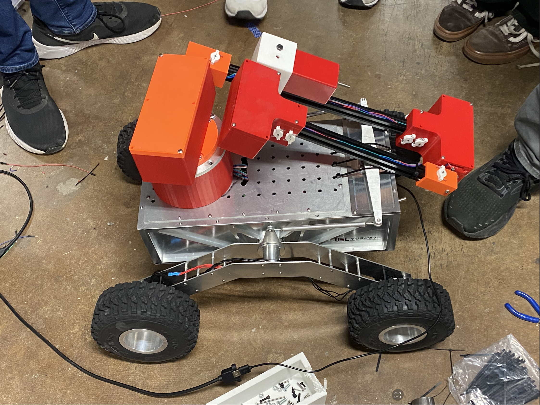
For this project, I served as a mechanical lead for the Rice Robotics lunar rover team. Our goal was to retrofit and develop a lunar rover for autonomous exploration tasks, including navigation, regolith interaction, and sample collection. We received part of the rover from the Unmanned Exploration Laboratory in South Korea, but much of the system needed to be redesigned, adapted, and integrated for demonstrations, future rover competitions, and the ODEK Engineering Showcase.
My work focused on the mechanical design and integration of the rover’s robotic arm and sampling system. I helped guide mechanical development, created and revised CAD models, performed torque and motor sizing calculations, evaluated gearbox reductions, tested available motors, and supported the transition from early sketches to physical prototypes mounted on the vehicle.
Background and Project Goal:
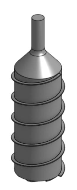
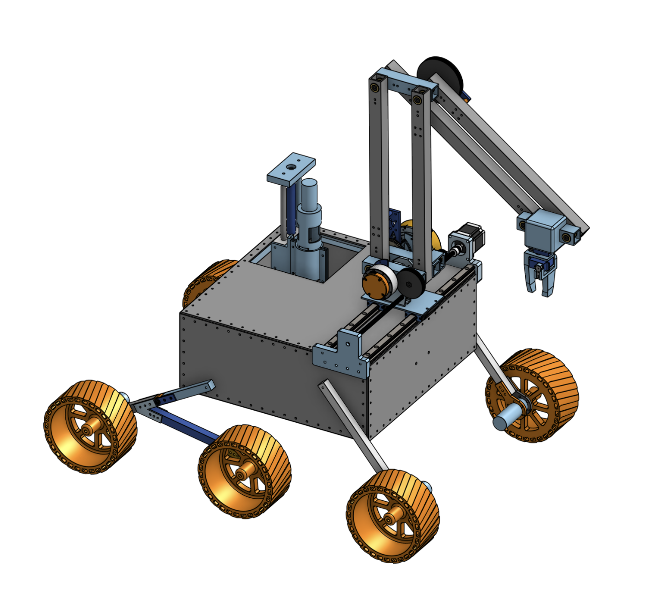
This project was motivated by the growing interest in long-term lunar exploration, which depends on the ability to navigate rough terrain, locate useful resources, and collect samples from environments such as craters, lava tubes, and permanently shadowed regions. Our rover concept was built around this challenge, aiming to create a compact robotic system capable of driving, positioning a sampling arm, drilling or coring into regolith, and storing collected material onboard.
Since the rover was partially inherited, we had to determine which components could be reused, which needed to be redesigned, and how to make the system reliable enough for public demonstrations and future competition development. This made the project less about designing every subsystem from scratch and more about real-world retrofit engineering, where mechanics, packaging, hardware, and team timelines all shaped the final design.
Initial research:
Our early research focused on studying existing lunar and planetary rover systems to understand what types of arm layouts, sampling tools, mobility choices, and control architectures have worked successfully in past exploration vehicles. Instead of trying to copy high budget aerospace designs directly, we looked for ideas that could be adapted in a cost efficient and realistic way using the tools and resource that we had at the ODEK or could get online.
On the mechanical side, this meant comparing different arm geometries, joint layouts, drill concepts, and sample handling methods while thinking about what we could actually manufacture, assemble, and test. Since we did not have access to large CNC’s or costly specialized materials, we focused on designs that could be built with CAD, 3D printed parts, aluminum extrusion, available motors, donor components, and simple fabrication methods. This stage helped us choose a practical direction for the rover arm and sampling system while identifying the main design challenges, including arm reach, joint torque, drill packaging, motor selection, stiffness, and integration with the rest of the rover.
Initial prototyping:
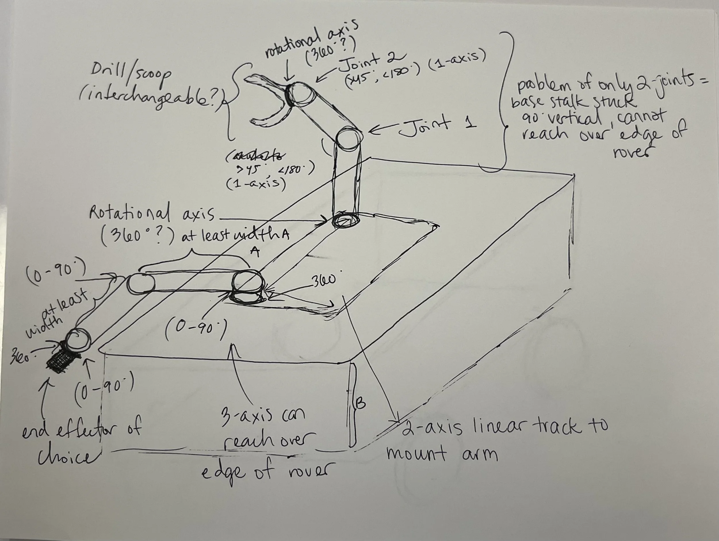
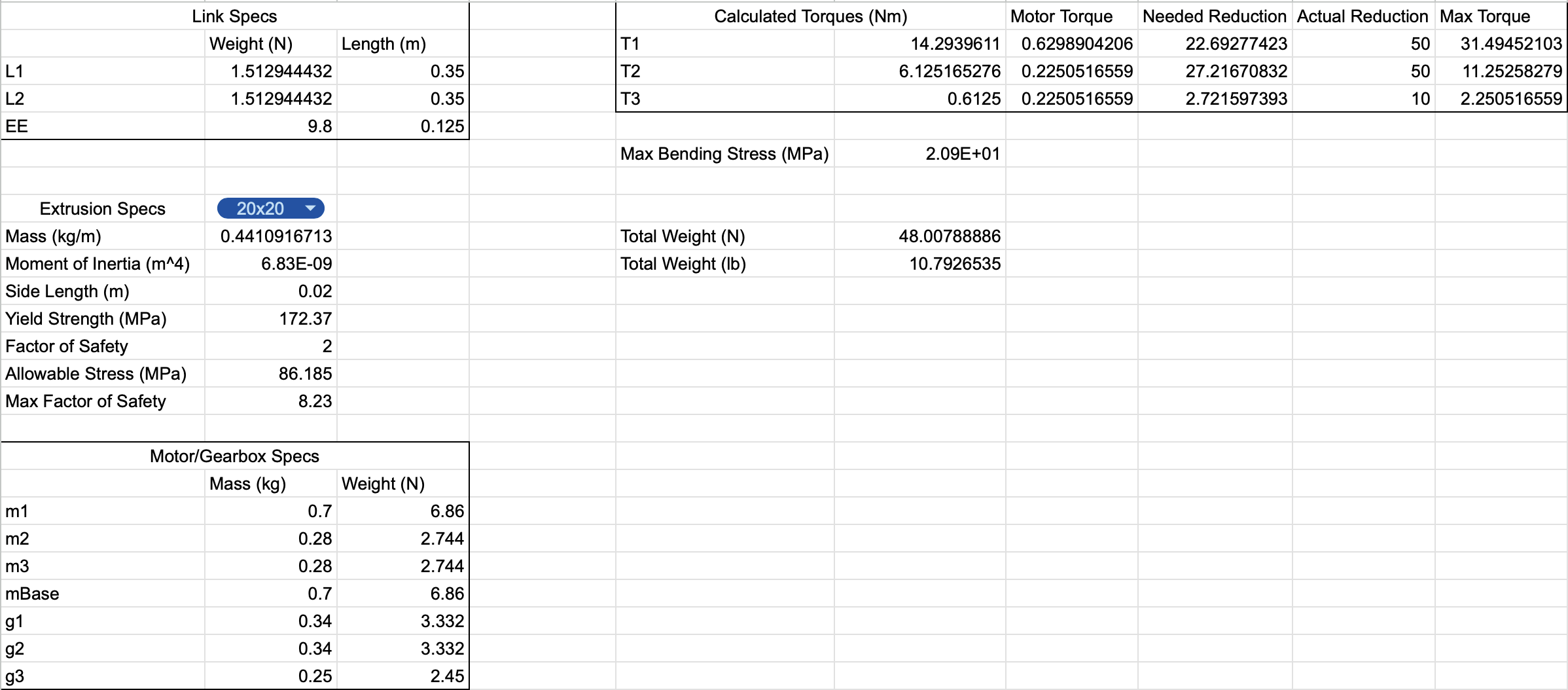
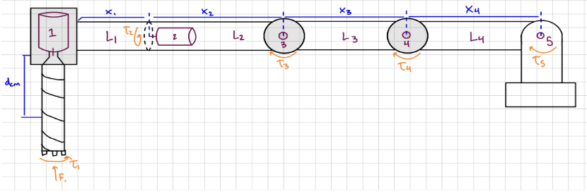
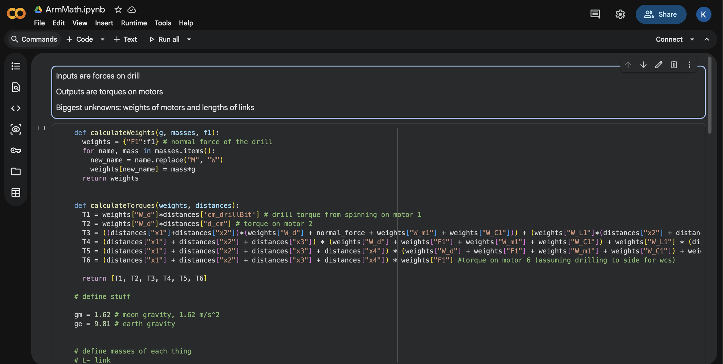
The mechanical work began with rough sketches of the arm geometry and torque calculations for each joint. I estimated link lengths, component weights, drill and end-effector loading, and the required torque at the shoulder, elbow, wrist, and drill. We checked these requirements for both Earth gravity testing and lunar gravity operation so the design could work for demos while still matching the long-term lunar rover goal.
One of the main early challenges was insufficient torque. To address this, we selected NEMA 23 stepper motors for the shoulder and elbow because those joints carried the largest loads near the base of the arm. We used a lighter NEMA 17 stepper motor at the wrist because the torque requirement was lower and reducing weight near the end of the arm helped reduce loading on the rest of the system. We also used purchased gearbox attachments, including 50:1 reductions for the higher-load joints and a 10:1 reduction for the wrist.
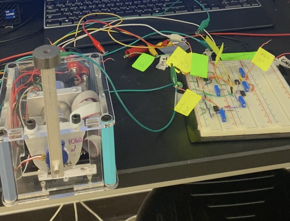
Because some motors came from the ODEK donor depot and others were purchased as needed, we did not rely only on datasheet values. We built a pony brake dynamometer to test several available motors and compare their measured torque to the reported values. The results were generally close to the datasheets, which gave us more confidence in our motor and gearbox choices before moving further into CAD and fabrication.
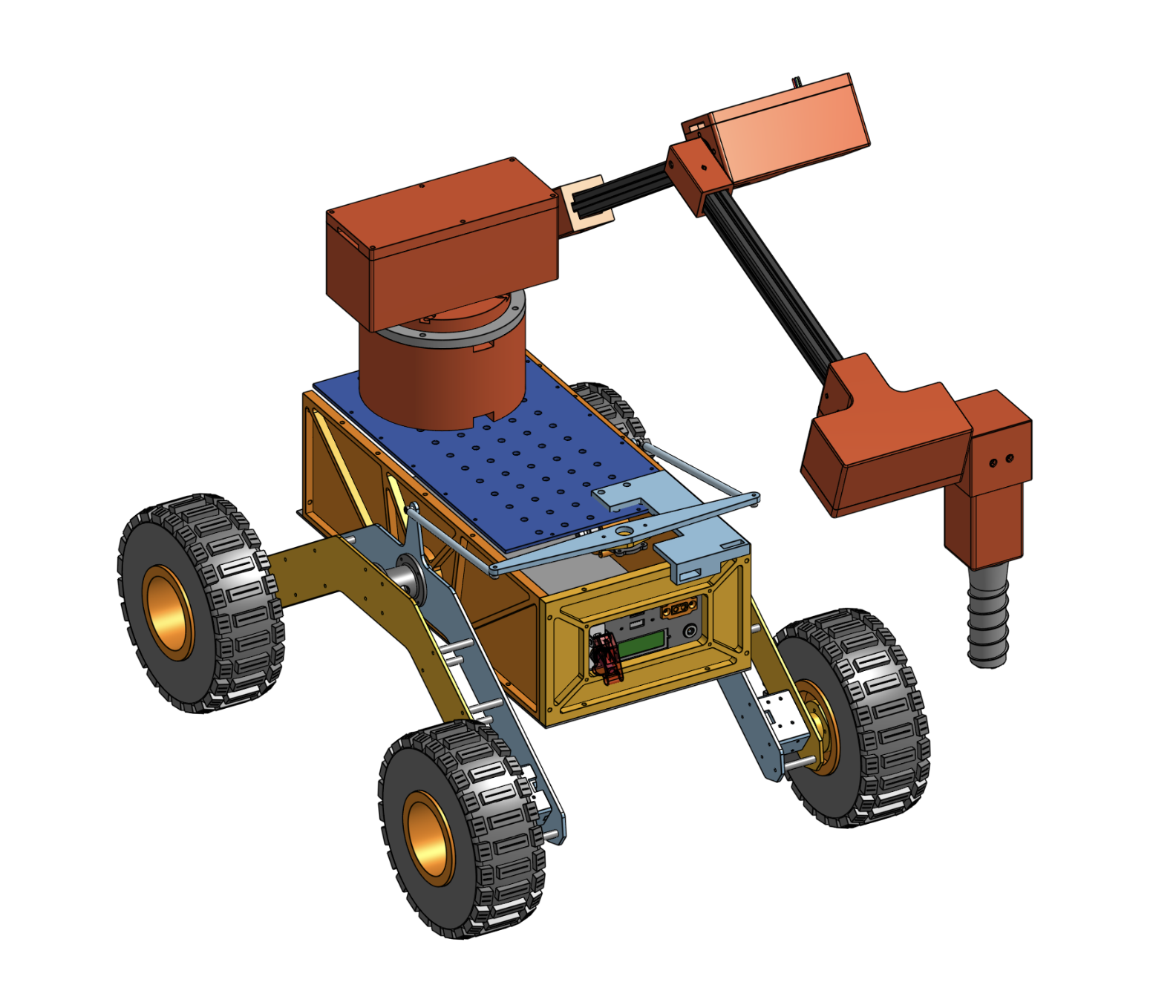
Mechanical Design:
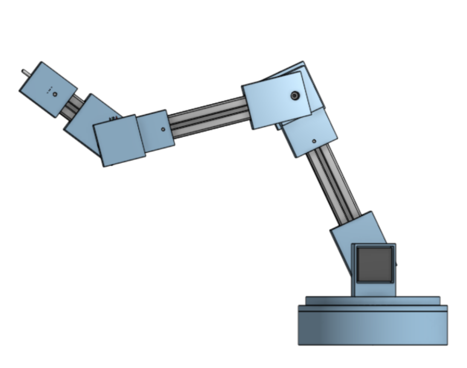
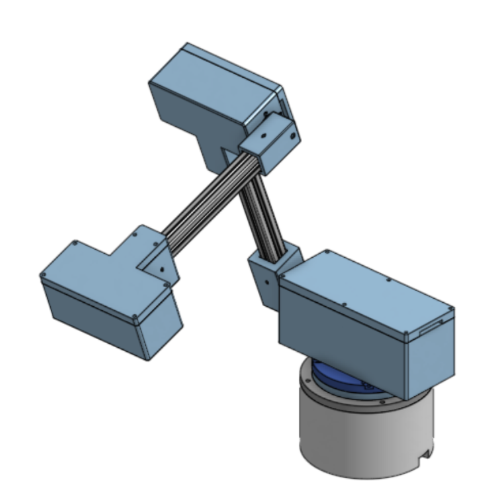
After the initial calculations, we moved into CAD development and physical prototyping. The arm used aluminum extrusion links, motor-driven joints, high-reduction gearboxes, and modular 3D-printed housings to package the actuators and connect the arm to the rover chassis. I worked on turning the rough arm concept into parts that could actually be manufactured, assembled, adjusted, and tested.
A major part of the design process was packaging the motors, gearboxes, joints, and drill hardware into a compact arm that still had enough reach for sample collection. The shoulder and elbow joints needed stronger motors and larger reductions, while the wrist needed to stay lighter so it would not overload the rest of the arm. We also had to consider motor alignment, shaft support, fastener access, wiring paths, and whether the arm could move through its range without interfering with the chassis or wheels.
This stage showed how vastly different the design was once we moved it from CAD into hardware. Small decisions like where to place a motor, how to support a gearbox, how to route wires to the ESP32 motor controllers, or how to make a housing easy to fasten had a large effect on whether the system was easy to integration. Each iteration helped make the arm more practical, testable, and better prepared for functionality.
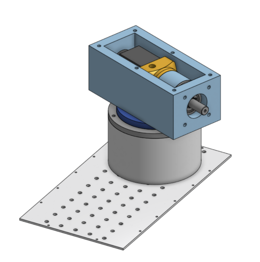
System Integration:
After the arm prototype was assembled, the next challenge was mounting it cleanly onto the rover and making sure it could work with the rest of the system. We used a lazy Susan bearing at the base to support rotation and help distribute the arm load into the chassis. This made the base joint more stable while keeping the design simple and realistic to fabricate.
A lot of the integration work came down to practical details like fastening, alignment, and wiring. The arm needed to be securely bolted to the chassis, the joints had to stay accessible for adjustment, and the wiring had to be routed so it would not interfere with rotation or the arm’s range of motion. This stage helped me understand how much of robotics design depends on the small mechanical details that make a system easier to assemble, test, troubleshoot, and demonstrate.
Outcome and Next Steps
By the end of the Spring Semester, we had completed the lunar rover system for the ODEK Engineering Showcase, including a mounted robotic arm, sampling concept, controls architecture, and continued autonomy development. The project gave Rice Robotics a stronger starting point for future rover competitions by converting an incomplete inherited system into a more integrated and testable vehicle.
Even though we made a lot of progress throughout the year, the rover still required a lot of future work to get fully functional, including improvements to the arm’s stiffness and reliability, refinements to the drill and sample storage system, testing the rover in more realistic terrain, and continuing development toward autonomous sample collection. Additional mechanical work would likely focus on more robust joint modules, stronger actuator selection, improved gear reduction, better cable management, and lighter, more compact arm packaging.
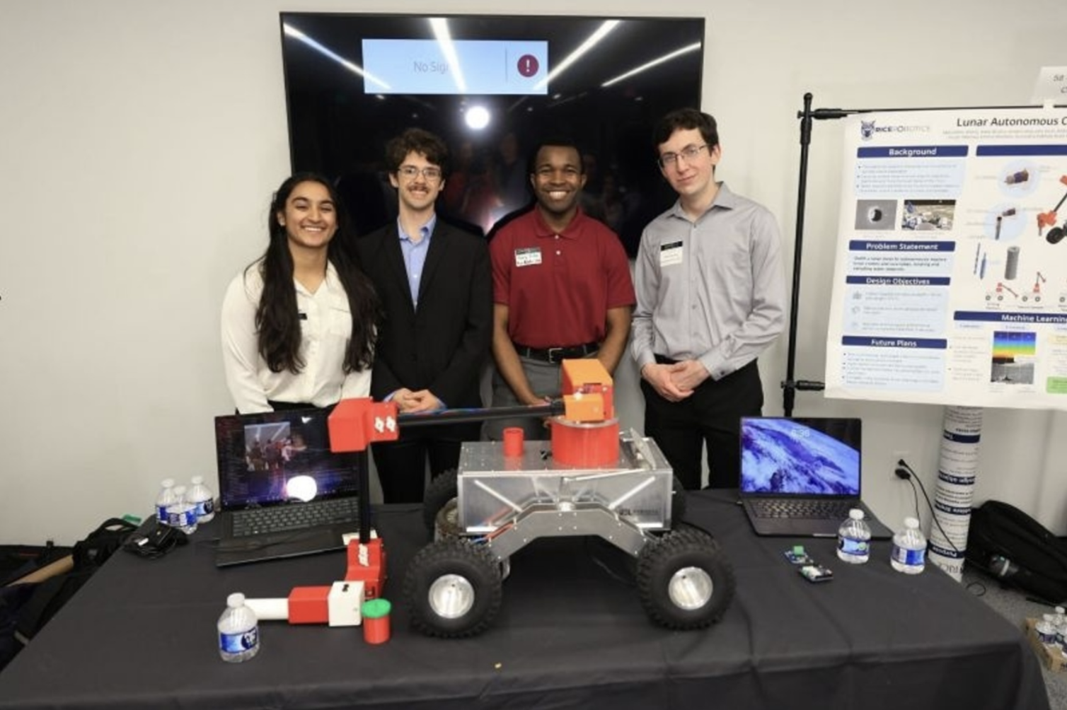
Lunar Rover Mech Team

Entire Lunar Rover Team


Rice Robotics Club - University Rover Challenge

Rice Robotics Club - Lunar Rover
Bubble CPAP Monitoring for Neonates
AUV Trim Weight System Design and Analysis
Analog and Digital Control of an Inverted Pendulum
Multi-body Dynamics Simulation of a Soccer Kick
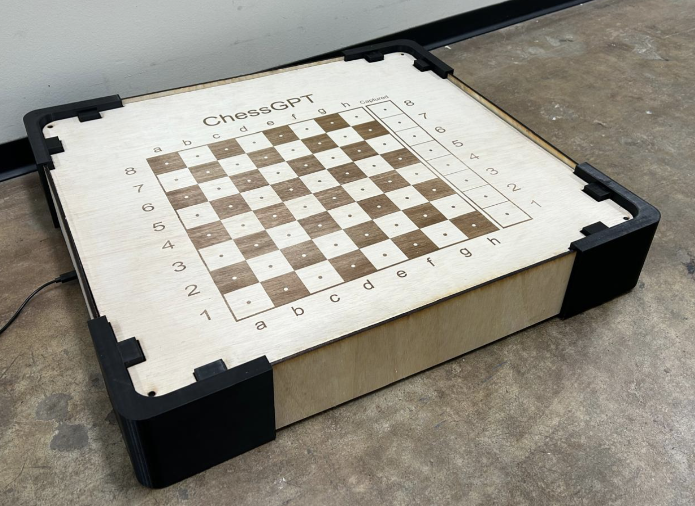
Chess GPT: The Self Playing Chessboard
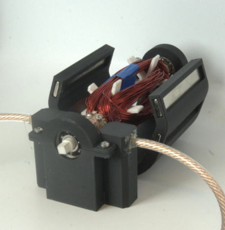
Custom DC Motor